Bosch Motronic ME7 dzinēja vadība par un ap

User avatar
mdz
Hektora liecinieki
Posts: 4887
Joined: 18 Nov 2014, 00:38
Gender: None specified
Contact:

Bosch Motronic ME7 dzinēja vadība par un ap

Postby mdz » 18 Oct 2015, 00:12

Principā topiks par un ap konkrēto dzinēja vadību, jautājumi, problēmas, risinājumi u.t.t.

Ok, vērsim pie ragiem - ir auto, principā 2 gabali ar ieswapotiem 1.8T AEB dzinējiem un uzliktu ME7.5 vadību. Problēma - auto tukšgaida purinās un @part throttle iet labāk kā @WOT. Viss atpas izņemot galvu un ieplūdes kolektoru (teorētiski arī sprauslas, bet to var izslēgt, jo vienam no auto ir uzliktas vadībai atbilstošās sprauslas) - AEB ir lielāki porti galvā, resnākas stabules kolektoram un iespējams lielāka kolektora krājtelpa. Piezīme: visiem ar ME7.5 vadītajiem dzinējiem ir mazāki porti galvā un šaurākas stabules kolektoram.

Izvirzītā teorija - dēļ lielāka galvas kanālu un kolektora tilpuma, kā paredzēts vadībā, telpā no droseles līdz vārstam (kam ME7.5 vadībā ir savs paramters/funkcija) ir mazāks gaisa spiediens, ka arī dēļ šaurākām kolektora stabulēm ir mazāks plūsmas ātrums, kas rezultējās mazākā cilindru aizpildijumā nekā to paredz/sagaida vadība. Konkrētās telpas spiediens un aizpildijums netiek mērīti, tie tiek rēķināti ņemot vērā diezgan garu sarakstu ar parametriem un kartēm.
Teoriju gandrīz pilnība apstiprina šodien izveiktais eksperiments uzliekot dzinējam ieplūdes kolektoru ar mazajām stabulēm. Dzinēja darbība uzlabojās, bet ne līdz galam. Te, visticamāk, nospelē fakts, ka galvas kanālu tilpums still ir lielāks kā domā vadība.

Uzdevums - atrast nepieciešamās kartes, konstantes, parametrus, kas atild par telpas tilpumu, tos pārrēķināt lai atbilstu reālajiem un izlabot programmu.

Tā kā ME7 vadība man nu jau gandrīz gadu ir aktuāls temats, esmu ievācis nedaudz informācijas un materiālu par ta darbību. Ir pieejams VAG R4 ME7.5 pilns funkciju apraksts vāciski un Alfa Romeo ME7.4 apraksts angliski. Laika gaitā ejot cauri konstatēts, ka lielākoties visas funkcijas abiem ir identiskas, tad principā Alfas dokumentāciju var izmantot lai saprastu čo pa čom jo vāciski es māku tikai lamāties, lasīt shēmas un s**g h**l. :crazy:

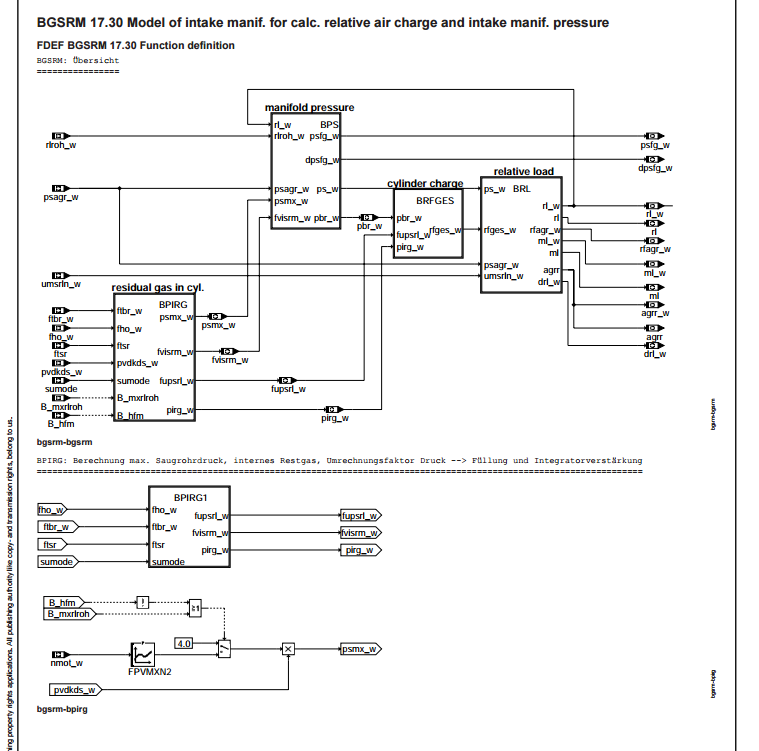
Parskrienot cauri dokumentācijai, šķiet, ka mums aktualā funkcija varētu būt BGSRM - Model of intake manif. for calc. relative air charge and intake manif. pressure
Image

Screenshotā redzamas divas no funkcijas shēmām, tālāk dokumentācijā ir atrakstīti arī visi paramteri, bet par to vēlāk.

Funkcijas apraksts stāsta:

The intake manifold model calculates the air charge in the combustion chamber from the air mass flowing into the
intake manifold.
An integrator simulates the storage of the intake manifold. It integrates the difference between the in-flowing relative
charge rlroh and the extracted relative air charge rl using the integrator constant KISRM, and delivers the standardised
air mass in the intake manifold at its output. The integrator is calculated in synchro. This acts like a multiplication of
the input variables by the engine speed. If the relative charges are used instead of the air mass flows as input signals, the
result obtained at the output is an intake manifold air mass.
With the temperature correction factor ftsr and the value for standard pressure 1013hPa the partial intake manifold
pressure of air mass and internal residual gas at a given air mass temperature in the combustion chamber is calculated from the
air mass. With an external EGR system, the partial pressure agrp w, generated by the external EGR, is added on. This produces the
total intake manifold pressure, which represents an important intermediate variable for other functions.
With the engine extraction equation rl = (ps - pirg) * fupsrl)*(100%-agrr) the extracted relative air charge rl is calculated from
the intake manifold pressure. In this way the relationship between the air charge rl and the intake manifold pressure
can be described by a straight line, calculated from the offset pirg and the slope characteristic starting value KFPSURL.
With active exhaust gas recirculation (EGR) the total charge signal rfges is corrected to the relative air charge rl by
multiplying-in the EGR rate.
The offset is interpreted as residual gas pirg, which remains in the combustion chamber. The offset is dependent on the engine
speed nmot and the overlap angle wnwue at systems with camshaft control. If the camshaft position is between the two extremes of
camshaft control, offfset value pirg is calculated by linear interpolation as function of wnwue.
As the ambient pressure falls, the proportion of residual gas falls. The offset is therefore reduced by the altitude factor fho.
The slope of the straight line at standard temperature is also dependent on the engine speed and the overlap angle wnwue at systems
with camshaft control. The slope is calculated by the same method as the offset. For calculation of the intake manifold
pressure ps to the relative airr charge, the current air temperature in the combustion chamber must additionally be taken into
account. This is done using the factor ftbr. The faktor fupsrl = ftbr * KFPSURL takes into account all influences on the slope in
translation of pressure into air charge. The factor fupsrl is also provided for other functions.
With an external EGR system the calculation from intake manifold pressure to air charge delivers the total charge rfagr including
the EGR portion.
The extracted air mass rl is reduced by the EGR rate agrr. Then: rl = rfagr * (1-agrr).
rl is fed back to the input of the integrator as the extracted air charge. rl is the central variable for calculation of the
injection. The extracted air mass flow ml is obtained from the product of engine speed, rl and the constant KUMSRL.
The incorporation of the EGR partial pressure into the intake manifold model allows for calculation of the EGR portion of the
combustion chamber charge with the appropriate timing. The associated integrator for simulation of the storage behaviour of the
intake manifold referred to the EGR charge is to be found in the function BGAGR.


Ļoti pieļauju, ka visproduktīvakais variants būtu savākties pie kāda alus tilpuma un ņemot talkā skaitļošanas tehnikas vienību kura glabājās abas vadību dokumentācijas un apspriest šo visu, bet bring it on. Pieiesim problēmai no pareizās puses, jo uzpogāt dzinējam mazo kolektoru un mazo portu galvu būtu so diesel :hihi:
Powered by Hektors & Divi litri
Listen to SLAYER

User avatar
mdz
Hektora liecinieki
Posts: 4887
Joined: 18 Nov 2014, 00:38
Gender: None specified
Contact:

Bosch Motronic ME7 dzinēja vadība par un ap

Postby mdz » 18 Oct 2015, 01:31

Velviena funkcija, kas varētu būt aktuāli - BGMSZS - Calculation of mass flows into intake manifold

The section BGMSZS calculates the air mass flow into intake manifold.
This section is providing the calculation for different systems. Turbo charged and natuaral asperated engines as well as air mass
flow or pressure based systems.
The necessary funtionallity of the configuration can be defined by the system values SY Turbo and SY EGFE which are explained in
the section %PROKON. The following configuration is valid:
SY Turbo=1 --> Turbo charged engine SY Turbo=0 --> Natural asperated engine
The system value SYS EGFE is specifiing different compoments (systems) mounted on the engine or not:
HFM, ambient pressure sensor, intake manifold pressure sensor, induction system pressure sensor
SY EGFE -> Bit0: HFM present
Bit1: Pressure sensor post throllte body
Bit2: Pressure sensor pre throttle body
Bit3: Ambient pressure sensor;Pu-Sensor
Example: System with HFM and ambient pressure sensor BIT 3 2 1 0
-------------------------------
1 0 0 1 -> SY EGFE = 9
The calculation is done according to the following explanation.
1) air mass flow measured by air mass flow sensor HFM if sensor is ok (B hfm = true):
The air mass measured bei HFM is corrected by adding the air fuel mixture flow from canister purge and then calculated into
relative air charge. rlroh = ( mshfm + mste ) / ( KUMSRL * nmot )
2) air mass flow calculated as flow through throttle valve and bypass LLS
It uses the following physical relation:
The gas mass flow through a throttle valve is dependent on the opening cross-section, the pressure upstream of it, the gas
temperature and the ratio between the pressure upstream and downstream of the throttle valve.
Under standardised conditions the flow through a throttle valve is stored in a characteristic dependent on the opening angle or
the duty cycle. The standardised conditions are:
Gas temperature =0 degrees Celsius
pressure upstream of throttle valve pvdk = 1013hPa
pressure downstream of throttle valve ps < (0.5283 * pvdk)
The characteristic for the throttle valve (DK) is MSNWDK. It is a function of the throttle angle referred to the stop limit wdkba
at closed throttle valve.
The characteristic line for the idle speed actuator (ISA-bypass) is a function of
(a) in case of EWD/ZWD: duty cycle of the ISA (please refer to %ALLS)
(b) in case of stepper: actual position of the stepper (%ALLSTP)
With the temperature correction factor ftvdk the standard mass flow of the throttle valve msndk and the standard mass flow of the
canister purge valve msnte are calculated into the mass flow at current gas temperature.
The pressure correction factor fpvdk corrects the standard mass flow to the current pressure upstream of the throttle valve.
The pressure ratio pspvdk between the pressure downstream and upstream of the throttle body addresses the characteristic KLAF
(standardised flow through throttle valve), which at supersonic pressure ratios of pspvdk < 0.5283 delivers the value 1.
The gas velocity in this case is equal to the sonic speed. At pressure ratios of pspvdk > 0.5283 the gas velocity falls below the
sonic speed. The value from KLAF becomes < 1. Under consideration of this behavior, the actuel air flow through the throttle body
can be calculated. The KLAF-line at pspvdk values > 0.9 (full load) is very steep. This behavior results in big changes of the
air flow mssaug even there is only small pressure changes pspvdk. During an error of the HFM signal the value mssaug represents the
load (limp-home). For this reason it is necessay to limit the KLAF line to avoid swinging systems. A limitiation of the intake
manifold pressure calculation PSMXN in %BGSRM secures that during full load a not too high load value rl will be calculated.
The mass air flow over throttle body and idle speed actuator is normaly determinated by HFM if the load sensor is ready to
operate. The mass flow over TEV mste, which is not considered by load sensor, must be added to the mass air flow through
throttle body and ISA. The division by umsrln w = ( KUMSRL * engine speed) provides a primary signal for the relative charge
of cylinder.
Since adaptation of the throttle angle stop limit at closed throttle valve doesn’t occur frequently under actual operating
conditions (clamp 15 = true & nmot=0 & t>= 30 sec), an adaptation is carried out by means of a comparison of the air mass flow
measured with the HFM and the air mass flow calculated via the throttle angles and duty cycle of the ISA (only for systems with
bypass).
This "leakage air adaptation" will be released only under idle condition B ll=1 and when the main charge signal (!E lm) and
secondary charge signal (!E dk) are ok. With MSALLMX and MSALLMN the maximum and minimum air mass adaption ranges are defined
respectively.
Via factor KIMSALL the "leakage air adaptation" speed is set.
The output of the leakage air adaptation is added to the leakage air MSLG at closed throttle valve (wdkba = 0) and stored in the
variable msndko w. If the corrected air mass flow through throttle valve mssaug corresponds to the air mass flow measured
by HFM mshfm, the leakage air adaptation has been completed successfully.
For certain functionalities is necessary to use the calculated mass air flow through throttle valve and ISA as back up. For
determination of mssuag several variables ftvdk, fpvdk, msndko, msnlls and the char. line KLAF are used which adjust mssaug
within allowed ranges. Therefore the second load signal mssaug can be adapted to the main load signal mshfm. For this purpose
the difference mass flow msdif (=mshfm-mssaug) is formed and fed to an integrator. For msdif=0 the integrator provides the value
fkmsdk=1, otherwise fkmsdk is different from 1. The factor fkmsdk is used to adjust the pressure upstream throttle valve pvdkds.
In this way mssaug is adapted to mshfm.
The integrator is activated only by operation ready load sensor (!E lm) and second load signal (!E dk), and furthermore
the air mass ml must exceed the threshold MLFKMSDK. the limitations of the integrator are given by FKPVDKMX and FKPVDKMN.
Powered by Hektors & Divi litri
Listen to SLAYER

User avatar
Aig
Rakstītājs
Posts: 9710
Joined: 17 Nov 2014, 02:33
Gender: None specified
Contact:

Bosch Motronic ME7 dzinēja vadība par un ap

Postby Aig » 18 Oct 2015, 10:46

Tā kā es to dokumentāciju neesmu lasījis, baigi prasītos visu to saīsinājumu definīcijas. Dažas ir tajā tekstā pieminētas, bet ne visas. Vai tās ir pieejamas?

Taču par sākumā minēto problēmu - vai ir precīzi zināms, ko ecu izdara nepareizi brīdī, kad iestājas problēma? - degviela par daudz vai par maz, vai nelaikā, aizdedze nevietā ? Man tā kā gribētos izvirzīt apgalvojumu, ka ieplūdes parametri ir būtiski tikai pie izmaiņām motora darbībā, bet ne vienmērīgi darbojoties (piem. brīvgaita).

Savukārt par pašu motroniku - kāds to disasemblēt ir mēģinājis ?
Sūdi sākās kad aiziet powered by . :roll: (c)mdz
Un beidzas, kad aiziet raznosā.

User avatar
wth
Skarbais
Posts: 6934
Joined: 12 Nov 2014, 22:41
Gender: None specified
Contact:

Bosch Motronic ME7 dzinēja vadība par un ap

Postby wth » 18 Oct 2015, 11:07

Jā, saīsinajumi prasītos.

A man, toties, tikko pieleca, ka tas MAPs tak ir PIRMS droseles. Vakar visu vakaru mēģināju saprast, priekš kam tas ķēms vispār tur ir. Tā arī līdz galam nesapratu, bet iesaistīts viņš tiek daudzos dīvainos procesos.

Starp citu, dokumentācija, cik es viņu redzēju, apraksta ME7 kā tādu, gan atmo gan turbo gadījumiem, kā arī dažādās iespējamajās kombinācijās MAF/MAP-pirms-droseles/MAP-pēc-droseles un ko tik vēl ne, tā ka te vēl rūpīgi jāšķiro, ko ņemt vērā un ko nē.
Whiskey tango hotel
Kam gan ir nodarījusi pāri drusciņa gāzes?
Tagad ir labs brīdis aizbāzt visus savus caurumus ar salvetēm vai lupatām, lai tajos nekrīt instrumenti, skrūves, alva un citas lietas. Ja jau esi tam pieķēries, izdari to pašu arī motoram.

User avatar
mdz
Hektora liecinieki
Posts: 4887
Joined: 18 Nov 2014, 00:38
Gender: None specified
Contact:

Bosch Motronic ME7 dzinēja vadība par un ap

Postby mdz » 18 Oct 2015, 12:49

Ir visi apzīmējumi, tik hvz kā iepostēt, kopējot sanāk baigais rosols.

Disasemblēt ir mēģinājuši, pietam daudzi un sekmīgi. Es tādai operācijai gan vel esmu par stulbu, tb, mēģinājis esmu, bet līdz galam nesaprotu ko notiek.
Powered by Hektors & Divi litri
Listen to SLAYER

User avatar
mdz
Hektora liecinieki
Posts: 4887
Joined: 18 Nov 2014, 00:38
Gender: None specified
Contact:

Bosch Motronic ME7 dzinēja vadība par un ap

Postby mdz » 18 Oct 2015, 12:55

Powered by Hektors & Divi litri
Listen to SLAYER


Return to “Dzinējs / Kārba”

Who is online

Users browsing this forum: No registered users and 1 guest